Electronics (optional)
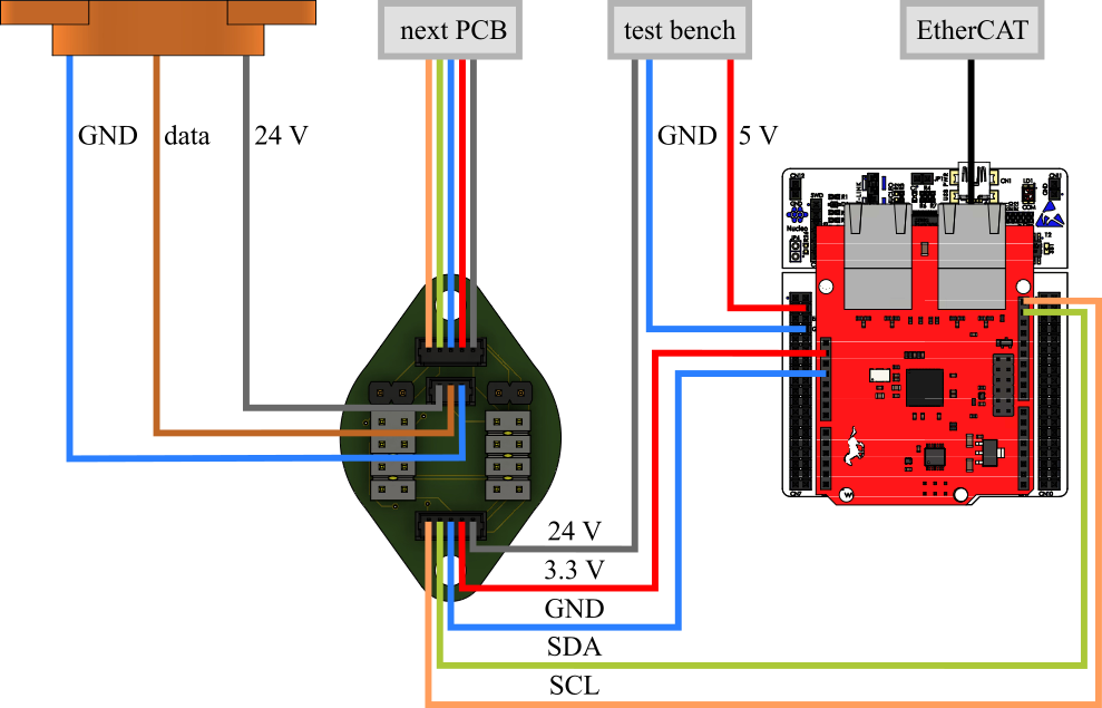
The optional PCB (mounted opposite each encoder in the joint) handles the modular communication of the encoders with the test bench via I2C. This allows a semi-modular SPONGE with 10 joints to be built. Each PCB comprises an AD-Converter (ADC) ADS122C04 to convert the analogue output of each encoder into a digital signal. Each ADC is configured as an I2C target (slave). As the I2C controller (master) serves a NUCLEO-F401RE development board, that is located outside the robot. Attached to it is a Bausano EasyCAT-shield that enables a connection from the NUCLEO board to the EtherCAT bus for communication with the test bench.
Circuit Board
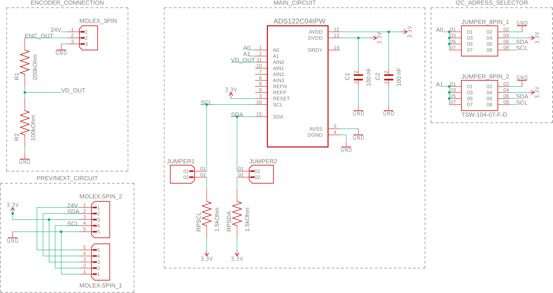
The circuit diagram shows the structure of the board. The ADC is composed of 16 pins. The device is powered with 3.3 V, and requires capacitors to ensure stable operation. The I2C lines (SDA and SCL) are provided with pull-up resistors. Given that only a single pull-up resistor is necessary for each line, jumper pins were incorporated into each circuit. Pull-up resistors can be integrated into the circuit by soldering them directly to it. The jumper pins can then be used for necessary connections. The ADC can be configured to one of sixteen possible I2C addresses via pins A0 and A1 (Table 14 in datasheet). This was also realized with jumper pins, thereby enabling flexible I2C-address assignment.
The Hall encoder is connected to the interface using a 3x1 Molex PicoBlade connector. Voltage dividers with resistances of 200kOhm and 100kOhm are necessary for downscaling the encoder signal (from 10 V to 3.3 V). It should be noted that the use of a buffer is unnecessary, as the ADC is already equipped with an integrated buffer. 5x1 Molex PicoBlade connectors facilitates the (daisy chain) connection of the PCBs. The PCB of the first soft actuator is connected with the NUCLEO development board.
Components
On PCB
| name | type | quantity per PCB |
|---|---|---|
| GCD21BR72A104KA01L | capacitor 0.1μF | 2 (C1, C2) |
| TNPW0805200KBHEA | resistor 200kOhm | 1 (R1) |
| ERA6AEB104V | resistor 100kOhm | 1 (R2) |
| TNPW08051K50BEEA | resistor 1.5kOhm | 2 (RPSCL, RPSDA) |
| ADS122C04IPW | AD converter | 1 |
| TSW-104-07-F-D | jumpers 4x2 | 2 |
| 61300211121 | jumpers 1x2 | 2 |
| PRT-09044 | jumper pin | 2* |
| 530470510 | Molex 5x1 FE | 2 |
| 530470310 | Molex 3x1 FE | 1 |
*4 for the first PCB (pull-up resistor connections)
Other
| name | type | quantity |
|---|---|---|
| NUCLEO-F401RE | development board | 1 |
| EasyCAT shield | EtherCAT interface | 1 |
| - | UART-TTL USB adapter (optional) | 1 |
| 15134-0501 | Molex 5x1 cable M-M | 1 |
| 15134-0301 | Molex 3x1 Cable M-* | 0.5 |
| - | jumper cable M-** | 5 |
*Only the M-side is required. Cable is cut in half and soldered to the encoder cable.
**Only the M-sides are required. Cables are cut in half and soldered to the Molex 5x1 cable M-M.
Manufacturing
The Gerber files can be directly sent to a PCB manufacturer. After that, we soldered the components onto the board ourselves.
Software
Please refer to the software section of the modular PCB. All necessary files for extending the existing test-bench software can be found in this folder. In order to use the semi-modular robot with the optional PCB, the following steps are required:
- Add encoder_block.mdl to your test_bench_sponge.mdl (and comment out unused blocks)
- Connect the NUCLEO development board to the computer via USB, and open the file ADS_code.ino using the Arduino IDE
- Compile and upload the code (ensure that EasyCAT.h and elapsedMillis.h is available)
According to its datasheet, the AD converter has an offset that can be calibrated by changing its configuration. In order to enable/disable this functionality, change the following code line:
// Enable offset calibration?
static const bool ENABLE_CALIBRATION = false;
The number of samples to be used for the calibration could also be set:
// Number of calibration samples
const int CAL_SAMPLES = 20;
The registries of the AD converter must be configured before use. This is done in the setup function of the program:
- Reg 0: (
0x81)- AIN0 vs AVSS
- gain=1
- PGA bypass
- Reg 1: (
0xDC)- 2000 SPS
- continuous mode
Reg 2 and Reg 3 are left at default. The I2C speed mode is set to “Fast Mode Plus” (1 Mbit/s).